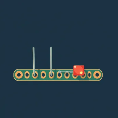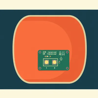
Daniel sent us this one — and it's a practical one. He's diving into his first real ESP32 project, a LoRa-based parking sensor with an ultrasonic detector and a temperature slash humidity sensor on the side. But what he's really asking about is GPIO headers. He's owned Raspberry Pis and other SBCs for years and just kind of ignored those rows of pins, and now he's realizing they're basically the whole point. He wants to know three things: what people actually use GPIO for, where the power limits are on these boards, and what sensors live on either side of that power divide. So where do we even start?
The GPIO header is the most overlooked feature on single board computers, and I get why. You buy a Raspberry Pi, you plug in a keyboard and a monitor, you've got a tiny desktop computer. The pins are just... But they're the thing that turns it from a computer into a controller. It's the bridge between software and the physical world.
It's the moment your spreadsheet stops being a spreadsheet and starts opening your garage door.
And Daniel's project is a perfect case study. He's building a parking sensor that talks over LoRa, so he's got an HC-SR04 ultrasonic sensor for detection, probably a DHT22 or BME280 for temperature and humidity, and an RFM95 LoRa module. Every single one of those connects through GPIO. So his question about what these headers actually do — he's about to live it.
The third question, about the power divide, is the one that separates a working project from a fried board. So let's walk through this in order. What are people plugging into these things, where do the power limits bite, and what sensors make sense on which side of that line.
Let's start with what GPIO actually is, because the name tells you almost everything. General Purpose Input Output. These are pins that your code can configure as either digital inputs, digital outputs, or — depending on the board — analog inputs, PWM outputs, or communication bus lines. The "general purpose" part is key. A USB port does one thing. An HDMI port does one thing. A GPIO pin does whatever you tell it to.
Which is also why it's intimidating. A USB port has a shape that matches a cable. A GPIO header is just a row of bare metal pins and a datasheet.
Right, and that's the barrier Daniel's describing. You look at it and think, well, what am I supposed to do with that? But once you know the patterns, it clicks. The most basic use is digital input — reading whether something is high or low, on or off. A button, a magnetic reed switch on a door, a PIR motion sensor. Those all just output a simple digital signal. Your code checks the pin and says, okay, someone pressed the button, or the door opened.
The world's fanciest light switch.
The fanciest light switch with an API. Then there's digital output, the flip side. You set a pin high or low to turn something on or off. An LED, a relay that switches mains power, a buzzer, or a MOSFET that controls a higher-power load. That's how you go from a logic signal to actually doing something in the physical world.
Daniel's ultrasonic sensor uses both of those at once.
That's what makes it a great teaching example. The HC-SR04 has four pins — VCC, ground, trigger, and echo. Trigger is a digital output. Your code sends a ten-microsecond pulse on that pin. The sensor then sends out an ultrasonic burst, and when the echo comes back, it raises the echo pin high. Echo is a digital input, and your code measures how long that pulse stays high. The duration is proportional to distance. Two GPIO pins, and you've got a rangefinder.
Which is absurd when you think about it. Two bare wires and a pulse-width measurement, and suddenly your parking spot knows whether a car is in it.
The temperature sensor Daniel ordered works differently but is still GPIO. If he got a DHT22, it uses a single digital pin with a proprietary one-wire protocol. The sensor sends a forty-bit data packet — sixteen bits for humidity, sixteen for temperature, eight for a checksum. Your code bit-bangs the protocol by rapidly switching the pin between input and output mode. It's not a standard protocol like I2C, it's just raw timing.
Which is charmingly hacky but also fragile. The DHT22 is the sensor equivalent of someone tapping out Morse code and hoping you're listening.
It has that annoying two-second sampling limit. You can't poll it faster than every two seconds, which is fine for ambient temperature but maddening if you're trying to debug. The BME280 is the more modern alternative. It uses I2C or SPI — proper communication protocols — and measures temperature, humidity, and barometric pressure. It draws about two point eight microamps in sleep mode and one point eight milliamps during active measurement. The DHT22 pulls about one point five milliamps during measurement and sixty to a hundred microamps in standby. Both are low enough to run straight off the board's power rail.
Daniel's got three devices — ultrasonic, temperature sensor, LoRa module — all talking to the ESP32 through different GPIO configurations. And the LoRa module is the most complex of the bunch.
The RFM95 is a perfect example of GPIO pins serving double duty. It communicates over SPI, which uses four pins — clock, data out from the controller, data in to the controller, and chip select. But it also needs a DIO zero pin for interrupt-driven receive, and a reset pin. So you're looking at six or seven GPIO pins for one module. SPI is the workhorse protocol for anything that needs speed — displays, SD cards, LoRa transceivers. I2C is the other big one, using just two pins for clock and data, and it's ideal for sensors because you can hang multiple devices on the same bus, each with its own address.
UART is the third one people bump into — transmit and receive, classic serial. GPS modules love UART.
Here's where the Raspberry Pi header gets interesting. The forty-pin layout is standardized across models, with twenty-six GPIO pins plus five-volt, three-point-three-volt, and ground pins. But many of those GPIO pins have alternate functions. Physical pin three and five default to I2C — that's SDA and SCL. Physical pin eight and ten are UART transmit and receive. So if you're wiring up a BME280, you'd use pins three and five for I2C and you're done. But if you need those pins for something else, you can reconfigure them. That flexibility is the whole point.
The ESP32 takes that even further, right? Thirty-four GPIO pins, but some of them come with baggage.
This is the first big misconception Daniel's going to run into. Not all GPIO pins are created equal. On the ESP32, several pins are strapping pins — GPIO zero, two, five, twelve, and fifteen. These pins are sampled at boot to determine things like boot mode and flash voltage. If you pull them high or low with an external circuit, you can prevent the board from booting. GPIO twelve, for example, has an internal pull-up resistor that sets the flash voltage. If you connect a sensor that pulls it low, your ESP32 won't start. It's the kind of thing that drives you insane because the circuit works fine once it's running, but it won't boot.
You spend three hours debugging your code, and the problem was a pull-up resistor you didn't know existed.
The Raspberry Pi has its own quirks. All the GPIO pins on the Pi are three-point-three-volt logic. If you connect a five-volt sensor output directly to a GPIO pin, you can damage the board. This is one of the most common mistakes, and it's the second big misconception — that five-volt sensors just work with three-point-three-volt logic. The HC-SR04 is a classic case. It's nominally a five-volt sensor, and its echo output can swing up to five volts. A lot of people connect it directly and it works for a while, but it's out of spec and can eventually fry the pin. The fix is a simple voltage divider — two resistors that drop five volts to three-point-three — or a dedicated logic level converter.
The first lesson of GPIO is: read the datasheet, and then read it again. The second lesson is: your board is more fragile than you think. Which brings us to Daniel's second question — where are the power limits?
This is where projects go from "why isn't this working" to "why is there smoke." Every board has a regulator that supplies the three-point-three-volt rail, and that regulator has a maximum current rating. On a typical ESP32 dev board, the three-point-three-volt regulator is rated for about six hundred milliamps total. That's for the board itself, the ESP32 module, and everything you connect to the three-point-three-volt pins. The ESP32 alone can draw up to five hundred milliamps during Wi-Fi transmit bursts. So if you're running Wi-Fi and you've got sensors pulling from the three-point-three-volt rail, you've got maybe a hundred milliamps of headroom before things get sketchy.
A hundred milliamps is basically a rounding error once you start adding peripherals.
Now, many dev boards also have a five-volt pin on the header, which comes straight from the USB input or an external supply. That five-volt rail can typically supply more current because it bypasses the three-point-three-volt regulator. On a Raspberry Pi four, the five-volt GPIO pins can supply up to one point two amps, but the three-point-three-volt pins are limited to about five hundred milliamps. So the pattern is: low-current sensors on three-point-three, higher-current devices on five volts, and anything power-hungry gets its own external supply.
Where does Daniel's project fall on that spectrum?
Let's do the math. The RFM95 LoRa module draws about a hundred and twenty milliamps during transmit at plus twenty decibel-milliwatts. The HC-SR04 draws about fifteen milliamps during active measurement and two milliamps quiescent. The DHT22 pulls one point five milliamps during measurement. Total worst-case draw is under a hundred and forty milliamps. That's well within the ESP32's budget, even with Wi-Fi running. Daniel can power everything from the board and be fine.
If he decides to add a servo to tilt the sensor or a relay to trigger something, he crosses the line instantly.
A typical hobby servo can pull five hundred milliamps or more under load. A relay coil draws seventy to a hundred milliamps. An LED strip can pull an amp or more. Those all need external power and a switching mechanism — a transistor or MOSFET for DC loads, or a relay for AC. And once you're mixing external power with the board's logic, you need to be careful about ground references. All the grounds need to be connected, or your signals won't make sense.
The ground connection is the thing that trips up beginners. You've got your external five-volt supply powering a servo, and you're controlling it with a GPIO pin, but you forgot to connect the external supply's ground to the board's ground. The signal has no reference, the servo twitches randomly, and you think your code is broken.
That's the third big misconception — that power and ground are independent. They're not. Every signal needs a return path. If your external supply's ground isn't tied to the board's ground, the GPIO pin's voltage is floating relative to the servo's reference. It's like trying to measure someone's height while they're standing on a different floor.
Alright, so we've covered the uses and the limits. Daniel's third question is about sensor selection — what lives on the board-powered side of the divide, and what needs external power.
On the low-power side, the options are extensive. For environmental sensing, the BME280 is the gold standard right now — temperature, humidity, and barometric pressure over I2C or SPI, drawing microamps in sleep. The DHT22 is the budget option, simpler to wire but less accurate and slower. For distance sensing, the HC-SR04 is the classic, but there are also laser time-of-flight sensors like the VL53L0X that use I2C and are accurate to millimeters. For motion, PIR sensors output a simple digital high when they detect movement and draw almost nothing. Magnetic reed switches for doors and windows are passive — they don't draw any power at all.
Passive sensors are the cheat code. A reed switch is just two pieces of metal that touch when a magnet is nearby. Zero power, infinite reliability, and it costs about fifty cents.
They're perfect for GPIO because they're just a switch. You configure the pin as an input with a pull-up resistor, and when the magnet moves away, the switch opens and the pin goes high. That's it. No protocol, no timing, no power budget. Daniel could add one to his parking sensor to detect whether a gate is open or closed, and it wouldn't change his power calculation at all.
On the other side of the divide, what are we looking at?
Once you need external power, you're usually driving something mechanical or high-current. Servo motors, stepper motors, solenoid valves, high-power LEDs, relays for AC loads. These all need their own supply, and they need a driver circuit between the GPIO pin and the load. A MOSFET is the standard choice for DC switching — the GPIO pin charges the gate, the MOSFET conducts, and the load gets power from the external supply. The MOSFET handles the current, not the GPIO pin.
The MOSFET itself draws essentially nothing from the GPIO pin. It's voltage-driven, not current-driven.
A logic-level MOSFET like the IRLZ44N will fully turn on with three-point-three volts on the gate and can switch tens of amps. The GPIO pin sees it as a tiny capacitive load — it charges the gate in microseconds and then draws nothing. It's the cleanest way to bridge the power divide.
Daniel's project, as currently specced, is comfortably on the low-power side. But what if he wants to add a display, or a buzzer, or some kind of indicator?
A small OLED display over I2C draws maybe twenty milliamps. A piezo buzzer draws a few milliamps. An LED with a current-limiting resistor draws ten to twenty milliamps. These are all still in the realm of board power. The threshold where you need external power is roughly when a single device draws more than a hundred milliamps, or when the sum of all your peripherals pushes past the regulator's headroom. For an ESP32 with Wi-Fi, I'd say keep your total peripheral draw under a hundred and fifty milliamps on the three-point-three-volt rail and you're safe. On the five-volt rail, you've got more room, but check the board's schematic.
The practical tip you always give is: measure it.
Before you commit to a design, power everything up on a breadboard and measure the actual current draw with a multimeter. Datasheets give you typical values, but your specific board, your specific sensors, your specific wiring — they all vary. A cheap multimeter in series with the power supply tells you exactly what's happening. It's the difference between confidence and hope.
Hope is not a power management strategy.
Hope is how you release the magic smoke. And magic smoke is expensive.
Let's pull this together into something Daniel can actually use. He's got an ESP32, an HC-SR04, a temperature sensor, and an RFM95 LoRa module. He's wiring them up on a breadboard. What's his checklist?
First, the power budget. His total draw is about a hundred and forty milliamps peak, well within spec. He can run everything from the board's five-volt and three-point-three-volt rails. Second, pin selection. He needs to avoid the ESP32 strapping pins — GPIO zero, two, five, twelve, and fifteen — or at least understand what happens if he uses them. Third, level shifting. The HC-SR04 echo pin outputs five volts, and the ESP32 GPIO is three-point-three-volt tolerant only. He needs a voltage divider on that echo line. Two resistors, ten-k and twenty-k, will drop five volts to about three-point-three. Fourth, the LoRa module uses SPI, so he needs to pick pins that support SPI or bit-bang it. The ESP32 has two hardware SPI controllers, and using them means faster, more reliable communication.
The temperature sensor — if he got the BME280, it's I2C, two pins, done. If he got the DHT22, it's one pin but he needs to deal with that two-second polling limit and the bit-banging library.
The BME280 is the better choice for a project like this. It's more accurate, it adds barometric pressure, and it uses a standard protocol that doesn't tie up the CPU bit-banging a custom waveform. But the DHT22 will work fine if that's what's in the mail. The key is knowing the trade-offs.
Once it's all wired up and working, there's one more trick that turns a weekend project into something you can actually deploy — deep sleep.
This is the battery life multiplier. The ESP32 can drop into deep sleep, where it draws about ten microamps. You configure a timer to wake it every, say, thirty seconds. It boots, takes a sensor reading, transmits over LoRa, and goes back to sleep. The whole cycle takes maybe two seconds. If you're running on a battery, that's the difference between changing it every day and changing it every six months.
Daniel's parking sensor doesn't need to be on continuously. A car doesn't appear or disappear in thirty seconds. So he can sample infrequently, sleep deeply, and his power budget becomes almost trivial.
That's the real art of embedded design. It's not just about connecting pins — it's about understanding the rhythm of your application. When does the thing actually need to be awake? Everything else is waste.
The GPIO header, which Daniel's been ignoring for years, turns out to be the gateway to all of this. Digital input, digital output, I2C, SPI, UART, PWM, pulse-width measurement, deep sleep wake-up — it's all just pins and code.
The pins are the easy part. The hard part is the thinking: what's my power budget, what voltage levels am I mixing, which pins have special functions, and when does my device actually need to be on. Those are the questions that separate a prototype that works on the bench from one that works in a parking spot for six months.
To Daniel's three questions: common GPIO uses are digital IO, analog input, PWM, and communication protocols like I2C, SPI, and UART. The power limits on an ESP32 are about six hundred milliamps total on the three-point-three-volt rail, with maybe a hundred to a hundred and fifty milliamps of headroom after the board's own draw. On a Raspberry Pi, the five-volt rail can do over an amp, but the three-point-three-volt rail is capped at about five hundred milliamps. And the sensor divide — low-power sensors like the BME280, DHT22, HC-SR04, and PIR modules can run straight off the board. Servos, relays, and high-power LEDs need external power and a MOSFET or driver circuit.
One more thing on sensor selection. When you're browsing the dizzying array of options Daniel mentioned, filter by protocol first. I2C sensors are the easiest to work with — two wires, multiple devices on the same bus, standard libraries. SPI is faster but uses more pins. One-wire and custom protocols work but they're more fragile and harder to debug. Start with I2C, branch out when you need to.
The BME280 over I2C is the sensor equivalent of a well-documented API. The DHT22 is the equivalent of a shell script someone wrote in 2003 that still works but nobody knows why.
Both have their place. The DHT22 costs about two dollars. The BME280 costs about five. For a parking sensor where you just want to know if it's hot, the DHT22 is fine. For a weather station where you care about accuracy, the BME280 is worth the extra three dollars.
The actionable advice for Daniel, and for anyone staring at a GPIO header wondering what to do with it: start with a power budget spreadsheet. List every component, its voltage, its max current, and whether it runs from board power or external. That one habit prevents ninety percent of hardware headaches. Prefer I2C or SPI sensors over custom protocols. Use a logic level converter or voltage divider when mixing five-volt and three-point-three-volt. And if you're running on batteries, deep sleep is not optional — it's the whole game.
Measure everything with a multimeter before you trust the datasheet. The datasheet tells you what the sensor should draw. The multimeter tells you what it actually draws, on your board, with your wiring, at your ambient temperature. That's the ground truth.
With all that in mind, here's the bigger question. Sensors keep getting cheaper, more capable, and more integrated. The BME280 packs three sensors and an I2C interface into a package the size of a grain of rice. Will we eventually reach a point where everything is a self-contained module with its own microcontroller and a high-level API, and GPIO becomes an implementation detail you never touch? Or does the flexibility of bare pins — the ability to connect anything to anything — mean GPIO stays essential no matter how polished the modules get?
I think GPIO is the common denominator that doesn't go away. Even the most integrated sensor module still needs power, ground, and some kind of communication interface. Those are GPIO pins. What changes is the abstraction layer. Twenty years ago you were bit-banging one-wire protocols by hand. Now you call a library function and get a temperature in Celsius. But the pins are still there, and knowing what they're doing is still the difference between a project that works and one that doesn't.
The pins are the API to the physical world. The library is just documentation.
Documentation is only useful if you know what you're trying to do.
Go look at the GPIO header on your board. You've probably been ignoring it. Figure out what you could connect today.
Now: Hilbert's daily fun fact.
In the nineteen eighties, seamounts near the Faroe Islands were found to host more than two hundred species of invertebrates, roughly forty percent of which were endemic — meaning they existed nowhere else on Earth.
Two hundred species of invertebrates living on underwater mountains near the Faroe Islands, and nearly half of them are locals only. a very specific census.
I have follow-up questions about who was counting, but I suspect I won't get answers.
This has been My Weird Prompts. Thanks to our producer Hilbert Flumingtop. If you enjoyed this, send your own weird prompt to the show at show at my weird prompts dot com. For Herman Poppleberry, I'm Corn. Go connect something.