Daniel sent us this one — he wants to talk about AC to DC adapter equipment for DIY projects, specifically building a constant-voltage enclosure to power something like a remote-controlled traffic light. The idea is you've got twelve-volt DC LEDs, a Raspberry Pi running an MQTT client to receive signals and switch the lights, and you need to safely get from wall power to that low-voltage DC side. He's asking three things: what enclosures and parts you'd need, how to verify safe low voltage with a multimeter, and how to physically assemble the whole hardware unit. And he's clear upfront — this is dangerous work, for qualified people following instructions.

He's right to lead with that. The moment you stop powering a Raspberry Pi project from a five-volt USB brick and start wiring an AC inlet into a box you're building yourself, you've crossed a line. You're not in breadboard territory anymore. One reversed live and neutral, one ungrounded metal chassis, one fuse rated too high — and you've got a fire hazard sitting on your workbench.
Or a shock hazard sitting in your hand. And the thing is, the projects that push people across that line are exactly the kind Daniel's describing. You want to control something physical — actual lights, motors, actuators — and five volts at half an amp from a phone charger just won't cut it. So you buy a twelve-volt power supply, you start looking at enclosures, and suddenly you're reading datasheets that assume you know what an IEC inlet is.
Which brings us to why this matters right now. Home automation and IoT tinkering have exploded. MQTT has become the default protocol for hobbyist device communication — it's lightweight, it's simple, and it plugs straight into platforms like Home Assistant. But all that enthusiasm is pulling people into twelve-volt DC and hundred-twenty or two-hundred-forty-volt AC territory, often without any formal electrical training or real understanding of what makes an enclosure safe.
The gap between "I followed a YouTube tutorial" and "I understand why this won't catch fire" is wider than most people think. You see builds where someone's mounted a bare power supply inside a wooden box with no ventilation, or they've cut the connector off a wall wart and taped the splice, or they're switching twelve volts directly from a Raspberry Pi GPIO pin and wondering why the magic smoke escaped.
The magic smoke is always the saddest part of any project post-mortem. But here's the thing — Daniel's question is actually perfectly timed. A traffic light with twelve-volt LEDs and a Raspberry Pi MQTT controller is the ideal entry point for learning AC-to-DC conversion safety. The voltages on the DC side are low enough to be in what the IEC 62368-1 standard calls Energy Source Class One — under sixty volts DC and under two hundred forty volt-amps. That's the safety sweet spot. But the AC side is still real mains power, so you have to do everything correctly.
What you're saying is this project sits right on the line between "safe to touch" and "will absolutely ruin your day if you're careless.
And that's what makes it such a good teaching project. You get the full experience of specifying an enclosure, selecting a proper AC-to-DC converter, fusing the input, wiring everything to code, and verifying the output with a multimeter — but the DC side is forgiving enough that a mistake won't kill you. A mistake on the AC side is a different story, which is why we're going to walk through this assuming you know how to kill power at the breaker before you open the box.
Let's frame the actual build. Daniel's traffic light uses twelve-volt DC LEDs, the kind you can get in standard red, yellow, green modules. They've got built-in current limiting, so they just want a steady twelve volts. You're not messing with constant-current drivers or resistor calculations for bare LED strings. You give them twelve volts, they light up. You cut the twelve volts, they turn off.
Which means the power supply side is refreshingly straightforward. You want constant voltage, not constant current. A lot of beginners grab the wrong thing here because both exist and they look nearly identical in product listings.
Constant-current supplies are for bare LEDs where you need to regulate the current to prevent thermal runaway. Daniel's LEDs have that handled internally, so he wants a constant-voltage supply — specifically the Mean Well LRS-35-12. It's an enclosed switching power supply, thirty-five watts, outputs twelve volts DC at up to two point nine amps. Universal AC input from eighty-five to two hundred sixty-four volts, so it'll work anywhere in the world. Screw terminals, no soldering required, and it's compact enough to fit in a reasonable project box.
The Raspberry Pi side — he's running Eclipse Paho, the standard MQTT client library for Python on the Pi. The Pi subscribes to topics like "traffic slash red" and "traffic slash green," receives JSON payloads telling it which light to switch, and then toggles GPIO pins that drive a relay board. The relays handle the actual twelve-volt switching.
That relay board is the critical isolation layer. The Pi's GPIO pins are three-point-three-volt logic and can source maybe sixteen milliamps. You cannot drive a twelve-volt LED directly from a GPIO pin — you'll fry the pin or the whole Pi. The relay board sits between the Pi and the LEDs, so the Pi only ever sees low-voltage logic signals, and the twelve-volt DC circuit stays completely separate.
That's the project in a nutshell. A Mean Well converter takes wall power and gives you clean twelve-volt DC. A Raspberry Pi running Eclipse Paho listens for MQTT commands. A relay board lets the Pi switch those twelve-volt LEDs without the two voltage domains ever touching.
What we're going to walk through today has three parts. First, the enclosure and all the components you need to spec. Second, how to use a multimeter to verify you're actually getting safe low voltage on the DC side, per the IEC sixty-two-three-six-eight-one standard. And third, the physical assembly sequence — the order you mount, wire, and test everything so you don't paint yourself into a corner.
Before we get into any of that, let's state the obvious. This episode assumes you know how to safely disconnect mains power at the breaker before opening the enclosure or touching anything on the AC side. If you don't know what that means or you're not confident doing it, stop here. Watch some basic electrical safety videos, learn to use a non-contact voltage tester, and come back when you're ready.
I'll add — if you're outside North America working with two-hundred-forty-volt mains, everything we're saying about fusing and wiring still applies, but your current calculations change. A thirty-five-watt supply at two hundred forty volts draws about a hundred and fifty milliamps instead of three hundred. Adjust your fuse accordingly. The principles don't change, but the numbers do.
One of the quiet advantages of this particular project is that the DC side sits comfortably inside what the standard calls ES1 — Energy Source Class One. Under sixty volts DC, under two hundred forty volt-amps. That means if you've verified everything correctly, the low-voltage side is safe to touch. It won't be comfortable if you bridge it with a sweaty finger, but it won't put you in the hospital.
That's exactly why this is the right entry point. You get the full experience of working with mains wiring, fusing, grounding, and enclosure design — but the part you'll actually be handling and probing during testing is in the safe zone. It's the training-wheels version of a skill that scales all the way up to industrial control panels.
Let's get into the parts. First decision you make is the enclosure, and this is where I see the most avoidable mistakes. People grab whatever plastic box is cheapest on Amazon, drill some holes, and call it done. That works until it doesn't.
Until it melts, or until a wire works loose and touches something it shouldn't, or until you realize you can't fit the power supply and the Pi and the relay board all in the same box without them rubbing against each other.
Minimum internal dimensions for this build — two hundred millimeters by a hundred fifty by eighty. That gives you room for the Mean Well LRS-35-12, a four-channel relay board, the Raspberry Pi, terminal blocks, and wiring, with enough air gap that nothing's crammed together. The material should be polycarbonate or ABS, and you want at least an IP54 rating — dust-protected and splash-resistant. Not because you're taking this thing outside in a rainstorm, but because IP54 means the seams and gaskets are tight enough that a stray wire clipping or a dropped screw isn't going to find its way into the AC terminals.
If someone insists on a metal enclosure because it looks nicer?
Then you bond the earth ground from the IEC inlet to the enclosure body with a crimp ring terminal and a star washer that bites through the paint. A metal box with a floating ground is a shock hazard waiting to happen. If the live wire ever touches the case, the breaker won't trip unless that case is earthed. Plastic avoids that problem entirely, which is why I recommend it for a first build.
Plastic box, IP54, two hundred by a hundred fifty by eighty minimum. What goes inside it?
The heart of the build is the Mean Well LRS-35-12. This is an enclosed switching supply — and "enclosed" matters here. It's got a perforated metal cover, built-in ventilation, and all the high-voltage bits are inside a factory-sealed chassis. You're not handling an open-frame supply where the AC terminals are exposed on a bare PCB. The LRS series is basically the standard recommendation for this class of project. Twelve volts DC output, two point nine amps, thirty-five watts, screw terminals for both input and output. And the universal input means it'll run on anything from eighty-five to two hundred sixty-four volts AC, so whether you're in North America or Europe, the same part number works.
We keep saying constant voltage for a reason. Daniel's LEDs have their current limiting built in. If he were wiring bare LED strings, he'd need a constant-current driver, and picking the wrong one would either under-drive the LEDs or burn them out.
That's a misconception that trips up a lot of beginners. They see "twelve-volt LED power supply" in a search result, grab a constant-current unit because it was cheaper, and then can't figure out why their lights flicker or won't turn on at all. Constant voltage gives you a steady twelve volts regardless of load, up to the supply's current limit. That's what you want when the device handles its own current regulation.
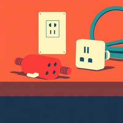
Moving upstream from the converter — the AC inlet. You want an IEC C14 socket with an integrated fuse holder. This is the same kind of connector you'd find on the back of a desktop PC power supply. The integrated fuse holder means the very first thing your mains power hits when it enters the box is a fuse.
That fuse is a five-by-twenty-millimeter glass cartridge, one amp, slow-blow. Here's the math: thirty-five watts divided by a hundred twenty volts is about zero point two nine amps. You multiply by a factor of three for the inrush current when the supply's capacitors charge up, and you get roughly zero point eight seven amps. Round up to one amp. The slow-blow characteristic handles that initial surge without nuisance tripping, but it'll still open fast enough if there's a real fault.
The fuse protects the wiring and the converter. What about a physical power switch?
An SPST rocker switch wired in series with the AC live wire, mounted on the enclosure wall. This gives you a hard disconnect without having to unplug the IEC cord. It's not a substitute for killing the breaker before you open the box — never is — but it's convenient for normal operation and it's one more layer of isolation.
On the DC side, you mentioned Wago lever nuts.
Wago 221-412, specifically. These are lever-actuated terminal blocks rated for thirty-two amps and they accept wire from twenty down to twelve AWG. For our DC wiring, we're using twenty AWG stranded, and the Wagos let you connect and disconnect without tools. Just lift the orange lever, insert the stripped wire, snap it down. They're vastly better than twist-on wire nuts for a project box where you might need to reconfigure things or troubleshoot. And at thirty-two amps, they're wildly over-spec for a two-point-nine-amp circuit, which is exactly what you want — the terminal block should never be the weak point.
The wire gauge itself — eighteen AWG stranded for the AC side, twenty AWG for DC.
Eighteen AWG stranded is standard for mains wiring in this power range, and the stranded part matters because solid-core wire in a project box that might get moved or vibrated can fatigue and break at the screw terminals. On the DC side, twenty AWG is plenty for two point nine amps over the short runs inside an enclosure. And wherever cables enter or exit the box, use strain reliefs — those little plastic glands that clamp onto the cable jacket so any tugging on the outside doesn't pull on the connections inside.
That's the power path. Wall to IEC inlet, through the fuse, through the rocker switch, into the Mean Well converter, out as twelve volts DC to Wago blocks. Now the control side — the Raspberry Pi lives entirely on the DC plane, powered by its own five-volt USB supply, never from the twelve-volt rail.
Never from the twelve-volt rail. I've seen people try to use a buck converter to step down the twelve volts to five for the Pi, and it works electrically, but it couples the Pi's power to the same supply that's driving the LEDs. If a relay coil kicks back or an LED channel shorts, your controller goes dark. Keep the Pi on its own isolated USB power. It's a few extra cents for a separate wall adapter and it eliminates a whole category of failure modes.
The Pi talks to the LEDs through a relay board, because the GPIO pins can't switch twelve volts directly.
The GPIO pins on a Raspberry Pi are three-point-three-volt logic with a maximum source current of about sixteen milliamps. That's enough to light a small indicator LED, not enough to drive a relay coil. So you use a four-channel five-volt relay module — the kind with optocouplers and transistor drivers already on board. The Pi's GPIO connects to the module's input pins, the module's relays switch the twelve-volt DC to the LEDs, and the two voltage domains never meet. The relay coils are driven by the module's own five-volt supply, which you can pull from the Pi's five-volt pin or from a separate rail. The GPIO just provides the logic signal.
The Pi sends a three-point-three-volt signal to the relay module's input pin, the onboard transistor switches the five-volt relay coil, and the relay contacts close the twelve-volt circuit to the LED. The Pi never sees anything above five volts. It's a neat little optoisolated handshake.
The MQTT side of this is where it gets satisfying. The Pi runs the Eclipse Paho client library in Python, subscribes to topics like "traffic slash red" and "traffic slash green." A remote publisher — could be a smartphone app like MQTT Dash, could be a command-line mosquitto underscore pub from your laptop — sends a JSON payload. Something like open brace quote light quote colon quote red quote comma quote state quote colon quote ON quote close brace. The Pi parses that, sets the corresponding GPIO high, the relay clicks, and the red LED gets twelve volts.
The latency on that is what, under two hundred milliseconds typically?
On a local network with a broker running on the same Pi or a nearby machine, you'll see the relay click within maybe fifty to a hundred milliseconds of hitting send. Even going through a cloud broker, you're usually under two hundred. For a traffic light, that's effectively instant.
Alright, so we've got our parts list. The enclosure, the Mean Well converter, the fused IEC inlet, the switch, the Wagos, the relay board, the Pi. Everything's picked out and sitting on the bench. Now the question Daniel actually asked: how do you verify with a multimeter that what you're about to touch on the DC side is actually safe low voltage?
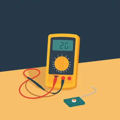
This is the step that separates a careful build from a hopeful one. And the multimeter is the single most important tool on your bench for this project — more important than the soldering iron, more important than the screwdriver. If you don't own a decent digital multimeter, stop and get one before you touch anything with mains power. Even a thirty-dollar unit from a reputable brand will do what we need.
The procedure starts before you've wired a single thing. Set your multimeter to AC voltage, two-hundred-volt range. With the breaker still off and the IEC cord unplugged, probe the inlet terminals where the mains wires will connect. You should read zero volts AC. If you read anything, your breaker isn't off or you've got a wiring problem upstream. Do not proceed until you see zero.
This is the "trust but verify" moment. Breakers can be mislabeled. Panels can be confusing. The meter doesn't lie. Once you've confirmed the inlet is dead, you wire the AC side — inlet to fuse, fuse to switch, switch to the converter's L and N terminals, earth to the converter's ground screw. Then, with the enclosure still open but the AC wiring complete, plug in the IEC cord, turn on the breaker, and flip the rocker switch. The converter should power up — you'll usually hear a faint high-frequency whine or see an indicator LED if it has one.
Now you probe the DC side.
Switch the multimeter to DC voltage, twenty-volt range. Probe the converter's V-plus and V-minus output terminals. You should see twelve volts DC, plus or minus five percent — so anywhere from eleven point four to twelve point six volts. If you're seeing something wildly different, like five volts or twenty-four volts, you've got the wrong supply or a faulty unit. Power down and figure it out before going further.
The ripple check — this is the one most hobbyists skip.
They shouldn't. Switch your multimeter to AC voltage while still probing the DC output. A well-filtered switching supply should show less than a hundred millivolts AC ripple on the DC rail. If you're seeing several hundred millivolts or more, the supply's output filtering is inadequate or failing, and that ripple can cause erratic behavior in your LEDs or relay board. The Mean Well LRS series is typically very clean — under fifty millivolts ripple in most real-world measurements — but you verify anyway.
You've got clean twelve-volt DC. Now the safety standard part — how do you confirm this actually qualifies as safe low voltage?
The relevant standard is IEC sixty-two-three-six-eight-one, which defines something called ES1 — Energy Source Class One. The thresholds are under sixty volts DC and under two hundred forty volt-amps. Our system is twelve volts at thirty-five watts, which is thirty-five volt-amps. We are comfortably, almost comically inside the ES1 envelope. But there's one more measurement that matters: leakage. Set your multimeter to DC voltage and probe between the DC negative output and the earth ground terminal. You should read very close to zero volts — ideally under half a volt. If you're seeing several volts, you've got leakage current finding a path to ground, which means the isolation between the AC and DC sides isn't working properly.
The AC and DC sides are galvanically isolated — there's no direct electrical connection between them. The earth ground on the AC side is a safety path, not a reference for the DC circuit.
Which brings us to the grounding strategy. For a plastic enclosure like we're recommending, the earth wire from the IEC inlet terminates at the converter's ground screw and stops there. The DC side floats — there's no connection between DC negative and earth. That's perfectly acceptable for this low-power project because the converter's internal transformer provides the isolation. For a metal enclosure, you'd additionally bond that earth to the enclosure body with a crimp ring terminal, so any fault that energizes the case has a path to ground that trips the breaker.
Floating ground on the DC side means if you accidentally touch the twelve-volt positive, you don't complete a circuit through your body to earth. You'd need to touch both positive and negative simultaneously to get a shock.
And at twelve volts, even touching both terminals with dry hands, you probably won't feel anything. The skin resistance is too high. But here's the misconception to kill: twelve volts is not always safe. If you short the output with a tool or a ring on your finger, a thirty-five-watt supply can deliver nearly three amps into that short. That's enough to heat metal red hot in seconds, cause burns, or create an arc flash. Low voltage doesn't mean no hazard — it means a different category of hazard.
The multimeter verification is a three-step ritual: confirm the AC inlet is dead before wiring, confirm twelve volts DC with low ripple after powering up, and confirm no leakage between DC negative and earth. You do all three, in that order, every time you open the box.
Now the assembly sequence. Order matters here, because if you mount the Pi and relay board first and then try to wire the AC side, you'll be reaching past delicate electronics with mains wire. The rule is: AC first, then DC distribution, then control electronics.
Step one, mount the IEC inlet and fuse holder in the enclosure. Most enclosures will need a rectangular cutout for the C14 socket — a step drill and a file will get you there. Step two is the AC wiring. From the inlet, the live wire runs through the fuse, then through the rocker switch, then to the converter's L terminal. Neutral runs directly from the inlet to the converter's N terminal. Earth runs to the converter's ground screw. That's the entire AC path — four connections, nothing branched, nothing shared. Keep these wires short and routed along the enclosure wall. Use eighteen AWG stranded, and crimp ferrules on the ends if your screw terminals will accept them.
The fuse orientation — it doesn't matter which side of the live wire it sits on, electrically. But convention puts it right after the inlet, before the switch, so the fuse is the first thing that sees current. If the switch itself shorts internally, the fuse still protects the downstream wiring. Step three, the DC distribution. The converter's V-plus and V-minus outputs go to Wago 221-412 blocks — one block for the positive rail, one for the negative. From those blocks, you branch out to the relay board's common terminals and to the LED negative returns. Every DC connection in the box terminates at a Wago, not at a screw terminal shared with something else. It keeps the wiring modular and makes troubleshooting trivial.
Step four, mount the Raspberry Pi and the relay board on nylon standoffs. These screw into the enclosure floor and hold the boards about six millimeters up, so nothing conductive touches the case. The Pi connects to the relay module with short female-to-female jumper wires — GPIO pins to the relay input pins, plus a ground reference between the Pi and the module.
Step five, the relay outputs. Each relay channel has three terminals: normally open, common, and normally closed. You wire the twelve-volt positive from the Wago block to the common terminal, and the normally open terminal to the LED's positive lead. The LED's negative lead returns to the negative Wago block. When the relay is off, the circuit is open and the LED is dark. When the Pi triggers the relay, the contacts close, twelve volts flows, and the light comes on.
That common negative return — all the LEDs share the same negative rail back to the converter. You don't need separate negative runs for each channel.
One negative bus, four switched positive channels. It's simpler and uses less wire. Step six is cable management. Bundle the AC wires together with a cable tie and route them along the left wall of the enclosure. Bundle the DC wires and route them along the right wall. Maintain at least a twenty-millimeter gap between the two bundles. This isn't just tidiness — it prevents a loose AC wire from ever contacting a DC terminal, and it makes it visually obvious which side is which when you open the box six months later to add something.
Before you connect the LEDs, you test everything with the multimeter one more time. Power up, trigger each relay channel from MQTT, and probe the output terminals. You should see zero volts when the relay is off, and somewhere between eleven point eight and twelve point two volts when it's on. If you see voltage leaking through when the relay is supposed to be open, you've either got a faulty relay or you wired the normally closed terminal by mistake.
Once that checks out, connect the LEDs and run a full MQTT test from your phone or laptop. Send a command to turn red on, confirm it lights. Send red off, confirm it goes dark. Cycle through all the channels. The relay should click audibly within about a hundred milliseconds of the MQTT publish. If there's a noticeable delay, check your broker connection — the Pi might be connecting to a remote broker over a slow link instead of a local one.
Alright, so we've walked through the parts, the multimeter verification, and the assembly sequence. Before we wrap up, let me give you three takeaways that'll make your next project safer and more reliable — whether it's this traffic light or something bigger.
First one: always verify the DC side with a multimeter before you touch it, even if the system's been running for hours. The Mean Well LRS-35-12 has output capacitors that hold a charge after you kill the AC power. They can sit at twelve volts for minutes after the breaker's off. If you're going to probe or rewire the DC side, discharge those caps through a one-kiloohm five-watt resistor across the V-plus and V-minus terminals. Touch the resistor leads to the terminals for a few seconds, then measure again to confirm zero volts. Skipping this step is how you get a surprise spark or a fried multimeter fuse.
Second takeaway: the fused IEC inlet is your single point of disconnection. Don't rely on the converter's internal protection alone — the one-amp slow-blow fuse on the AC side is what protects your eighteen AWG wiring from overcurrent and your converter from a fault downstream. If something shorts on the DC side and the converter's overcurrent protection fails to kick in, that fuse opens before the wiring heats up enough to melt insulation. It's a fifty-cent part that saves you from a fire.
Third: keep AC and DC wiring physically separated inside the enclosure. Left side AC, right side DC, with cable ties bundling each group. This isn't just about neatness. It prevents a stray strand of copper from bridging the two domains, it makes troubleshooting faster because you can see at a glance which side a wire belongs to, and if you ever hand this project to someone else to look at, they'll immediately understand the layout. A tidy box is a safe box.
If you build this exact traffic light project, you've got a rock-solid foundation for extending it. Add a pedestrian button — wire a momentary switch to a Pi GPIO pin with a pull-down resistor, write a few lines of Python to detect the press, and publish an MQTT message that triggers a crossing sequence. Integrate it with Home Assistant using MQTT auto-discovery — the Pi announces its topics and HA picks them up automatically. Or scale up to twenty-four-volt automotive LEDs using a Mean Well LRS-50-24, which is the same family, same form factor, just a higher output voltage.
The skills you learn on this build — specifying an enclosure, fusing an AC input, verifying isolation with a multimeter, keeping high and low voltage domains separated — those scale directly to bigger projects. Motor controllers, LED strip installations, home automation panels. You're not just building a traffic light. You're learning the electrical safety discipline that separates a hobbyist from someone who can design and build equipment that won't burn a house down.
On that cheerful note —
Here's the design challenge I'd leave you with. We've got one fuse protecting the entire AC side, which is correct. But what about overcurrent protection on each individual LED channel? If one of those twelve-volt lines shorts to the enclosure or a relay contact welds itself closed, the converter's overcurrent protection might catch it — or it might not before something melts.
That's the kind of question that separates a weekend project from something you'd actually leave plugged in when you're not in the room. You've got options. Individual one-amp glass fuses in inline holders on each positive LED lead — dead simple, totally effective, but you have to physically replace one if it blows. Or PTC resettable fuses, which are those little polymer discs that go high-resistance when they heat up from overcurrent and then reset themselves once they cool down. No replacement needed, but they're slower to trip and they leak a tiny current even when "open.
The third option, and the one I'd probably reach for first in a twelve-volt LED project, is current-limiting resistors sized for the specific LED forward voltage. If you know each LED module draws, say, two hundred milliamps at twelve volts, a sixty-ohm resistor in series limits the current to exactly that even if the LED fails short. It's not a fuse — it doesn't disconnect — but it prevents a runaway current situation. The downside is you're dissipating a bit of heat and you need to calculate the resistor value for your specific LEDs. None of these is universally correct. It depends on whether you prioritize fast fault clearing, automatic recovery, or simplicity.
That's the kind of engineering judgment call that the project forces you to make. You're not just following a wiring diagram anymore. You're thinking about failure pattern and deciding what kind of protection makes sense for how and where the thing will be used.
Which brings me to the bigger picture here. MQTT-based control is becoming the default for smart home devices. It's in Home Assistant, it's in commercial IoT products, it's in industrial automation. The line between hobbyist and professional electrical work is blurring fast. Ten years ago, building a networked control panel with an AC-to-DC supply, proper fusing, and isolated low-voltage outputs was something you'd only see in a professional integrator's shop. Now a motivated hobbyist can do it for under a hundred bucks in parts.
That's great, but it also means the knowledge floor has to rise. Knowing how to safely build a constant-voltage enclosure — proper fusing, proper grounding, verified isolation between AC and DC — that's not optional anymore. It's a foundational skill for anyone building IoT devices that plug into a wall. The traffic light is the training project, but the discipline transfers to everything from automated blinds to greenhouse controllers to home energy monitors.
If you build this project — or something like it — send us photos. We'll feature them on the website.
Now: Hilbert's daily fun fact.
Hilbert: In the seventeen-eighties, Russian fur traders in the Aleutian Islands reported finding hollow glass tubes in the sand after lightning storms — fulgurites — some over two meters long. Modern measurements show a lightning strike can fuse sand into glass at temperatures exceeding eighteen hundred degrees Celsius in under a second, which is about the same temperature as the Space Shuttle's nose cone during reentry.
Lightning makes glass hotter than a spacecraft.
The thing I keep coming back to is this: we're in a moment where the tools for building genuinely useful, connected hardware are more accessible than they've ever been. A Raspberry Pi, an MQTT broker, a thirty-five-dollar power supply, and an afternoon of careful work gets you something that would've been a commercial product costing hundreds a decade ago. But the physics hasn't gotten any more forgiving. Twelve volts is still twelve volts. A hundred twenty volts is still a hundred twenty volts. The electrons don't care how good your Python code is.
The electrons are the ultimate code reviewers. They don't do nuance.
They really don't. So learn to use the multimeter. Learn to spec the fuse. Learn to keep your AC and DC separated. Build the traffic light. Then build something harder. This has been My Weird Prompts. Thanks to our producer Hilbert Flumingtop. If you enjoyed this episode, leave us a review wherever you listen — it helps more people find the show.
I'm Corn.
I'm Herman Poppleberry. See you next time.

")